Heat-Loss Assessment · Sika Innsbruck

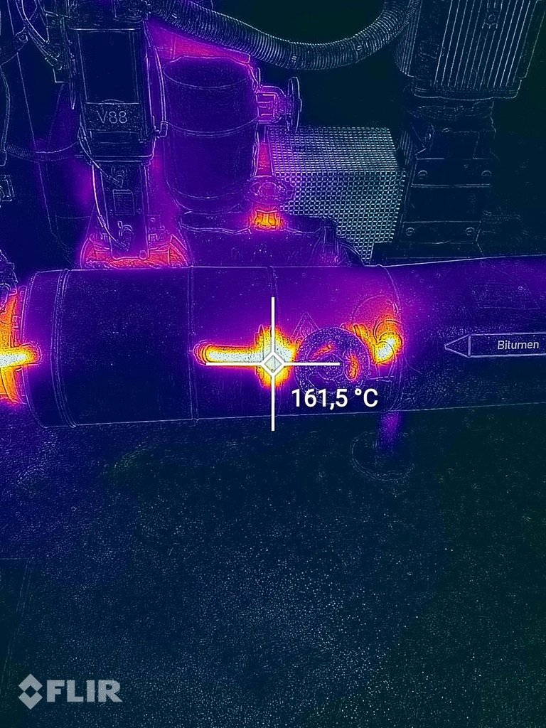
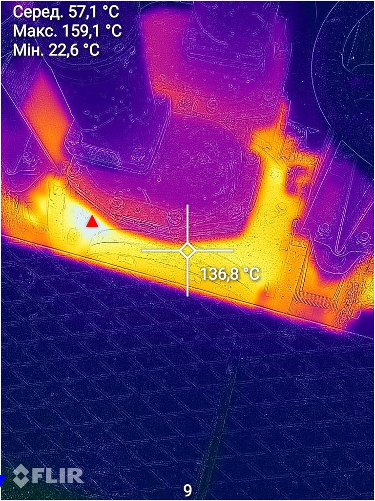
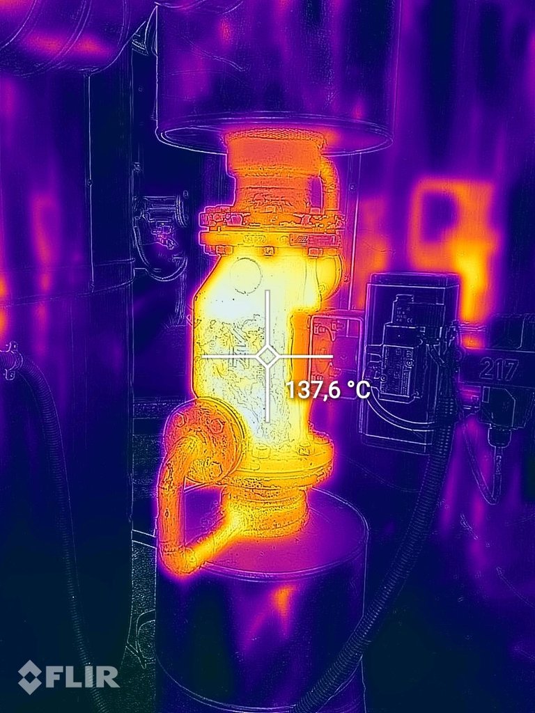
Save 96% of bitumen-line
heat losses with Inzonex.

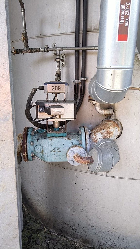
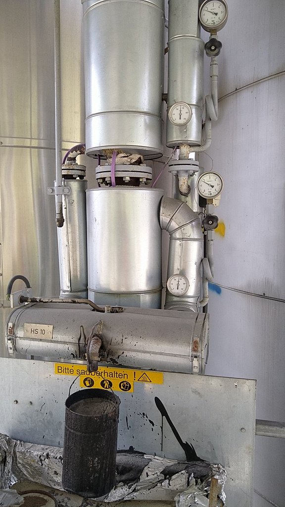
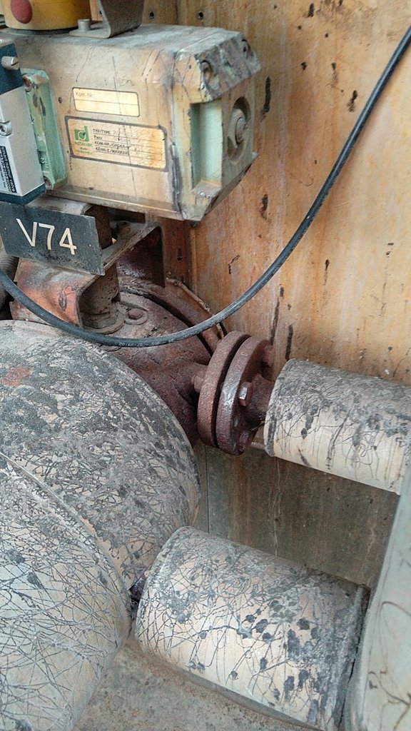
Sika Innsbruck · Tirol, Austria · Bitumen + Thermal Oil 220°C

Site survey 5 May 2026 · INZ-SIK-AT-2026-001

€38,500
Products + delivery
€71 K
€/yr saving
6.5 mo
Payback
292
t CO₂/yr avoided
Executive Summary

96.1% reduction across
167 bitumen-line elements

Site survey on 5 May 2026 covered the bitumen line (140–180°C operating zones) and the thermal oil distribution room (220–240°C) — 167 elements across both zones. FLIR thermal imaging measured surface temperatures up to 161.5°C on bitumen process pipes and gear pumps. Inzonex modular insulation delivers 96.1% heat-loss reduction, saving 1,425 MWh of fuel input per year at the gas-fired thermal oil heater.

Products + delivery
€38,500
167 elements · ex-works UA + DAP Innsbruck
Annual saving
€71,230
@ €50/MWh natural gas
Payback
6.5 months
Then pure profit, year after year
CO₂ avoided
292 t / yr
Scope 1 reduction · BAFA-compliant

Tune to your operating conditions

Adjust hours, gas price, thermal oil heater efficiency and CO₂ factor to see live savings.

Operating Hours / Year 8,760 h
8,760 h = continuous (24/7) · Bitumen plants typically run 8,000+ h/yr
Natural Gas Price (€/MWh thermal) €50/MWh
Austrian industry NG (2026): typical 40–80 €/MWh thermal
Thermal Oil Heater Efficiency 85%
Austrian industry NG-fired thermal oil heaters: typically 82–92%
CO₂ Emission Factor (t/MWh fuel) 0.205
Natural gas: 0.202 t/MWh (UBA) · diesel/oil: 0.27 t/MWh
Annual Energy Saved
1,425 MWh/yr
Fuel input saved (heater accounted)
Annual Cost Savings
€71,230/yr
At current gas price
🌍
Annual CO₂ Avoided
292 t/yr
EU ETS / BAFA-compliant
Project Reference

Site & conditions audited

All surface temperatures taken with calibrated FLIR thermal imaging. Heat-loss calculation uses Innsbruck climate (annual avg 9.5°C outdoor, 18°C indoor). Operating regime: gas-fired thermal oil heater feeds 220–240°C oil to bitumen tanks; bitumen line operates 140–180°C across multiple zones (storage, process, transfer).

ClientSika Innsbruck · Tirol, Austria
ReferenceINZ-SIK-AT-2026-001
Site visit5 May 2026
Plant typeBitumen storage & modification
Heat sourceThermal oil heater (gas-fired)
Operating mode8,760 h/yr (continuous)
Bitumen storage / indoor140°C (gauge-confirmed, 36 elements)
Bitumen process line175°C (FLIR surface 161°C, 99 elements)
Bitumen MOV / outdoor180°C (gauge-confirmed, 20 elements)
Thermal oil supply220–240°C (label-confirmed, 23 elements)
Insulation specStone wool 50 mm + PTFE-coated fiberglass outer

What we measured on 5 May 2026

Six general photographs of bare equipment and three FLIR thermal scans, taken across the bitumen line and thermal oil distribution room. The thermal imagery shows surface temperatures of 93–161.5°C on the elements scoped for Inzonex covers.

Heated ball valve 209
1. Heated ball valve V209 — thermal oil 220°C circuit, jacketed (AZ Armaturen)
Bitumen pump area
2. Bitumen line pump area — 2 tank flanges + DN25 fittings, fully bare
Gear pump assembly
3. Bitumen gear pump assembly — 2× ball valves + 0.4 m heated body, no insulation
Heated valve 217
4. Heated ball valve V217 — vertical, with pneumatic actuator + positioner
HS10 buffer
5. HS10 buffer vessel — 3 manometers showing 140°C, multiple bare flanges
MOV V74 outdoor
6. Motor-operated valve V74 — outdoor, exposed to weather, heavy rust
FLIR — bitumen pipe 161.5°C
FLIR 1. Bitumen pipe near valve V88 — 161.5°C measured (hottest)
FLIR — gear pump 159.1°C
FLIR 2. Gear pump body — max 159.1°C (avg 57.1°C surrounding)
FLIR — heated valve 217: 137.6°C
FLIR 3. Heated ball valve V217 body — 137.6°C
The Problem

Three losses, one root cause

Every uninsulated hot surface combines two heat-transfer paths — natural convection and radiation. Outdoor elements (most of the bitumen line) face additional forced convection from wind. None of these elements are currently covered.

161.5 °C

Surface temperatures up to 161.5°C

Bitumen pipes, gear pump bodies, heated ball valves — all running at 93–161.5°C exposed to ambient air. Personnel burn risk on every operating surface.

143.8 kW

Continuous heat loss, 24/7

Bitumen storage and circulation runs year-round. Every degree of ΔT bleeds energy through 167 element groups across both indoor and outdoor zones.

292 t / yr

CO₂ embedded in those losses

1,425 MWh of natural gas burned at the thermal oil heater to compensate for the leak — directly quantifiable on Sika's Scope 1 emissions footprint.

What's inside every Inzonex module

Modular removable insulation system designed for industrial heated equipment. Engineered for full retrofit access — every module zips/buckles open for valve servicing, then re-closes in minutes. Manufactured to fit each element from on-site survey measurements.

1

Stone wool insulation core

50 mm · λ = 0.040 W/mK @ 100°C

Industrial-grade mineral wool sized for the operating temperature. Non-combustible (Class A1 per EN 13501-1), continuous service to 700°C, no chloride contamination of stainless steel substrate.

2

PTFE-coated fiberglass outer cover

Continuous service −60 to +260°C

Chemical-resistant outer fabric — withstands bitumen contamination, fuel oil, hot water washdown. UV-stable for outdoor installation. Smooth surface for easy decontamination. Emissivity 0.85.

3

Stainless steel hardware

A2 / 316L grade

D-rings, buckles, lacing hooks — corrosion-resistant for outdoor and chemical environments. Designed for unlimited open/close cycles without fatigue.

4

High-temperature thread & lacing

Aramid (Kevlar) · 350°C max

Stitched seams use aramid thread rated above expected service temperatures. Lacing closures permit field adjustment without specialist tools.

5

Internal vapour/condensation barrier

Aluminium foil composite

Reflective inner layer reduces radiative heat transfer to the wool core and prevents moisture absorption. Critical for outdoor elements exposed to rain and condensation.

6

Bridging-factor reinforcement

Per VDI 2055-1 Anhang C

Modules account for bolts, valve stems, drain ports, gasket gaps. Each element gets a custom-fit pattern with extra wool depth where needed to maintain ≤45°C surface everywhere.

Methodology

How the numbers were calculated

Standard convection + radiation energy balance per element, per VDI 2055-1 and ISO 12241. Surface temperatures from FLIR camera (non-contact). All inputs and outputs documented per element in the calculation annex.

Convection — Churchill-Chu (natural) + Churchill-Bernstein (forced/wind)

Nu_natural = (0.60 + 0.387·Ra^(1/6) / [1+(0.559/Pr)^(9/16)]^(8/27))²
Nu_forced = 0.3 + 0.62·Re^0.5·Pr^(1/3) · (1+(Re/282k)^(5/8))^(4/5)

Outdoor elements use whichever h is higher (forced wins above ~1.5 m/s wind). Innsbruck annual average wind 2.5 m/s.

Radiation — Stefan-Boltzmann

q_rad = ε·σ·(T_surface⁴ − T_ambient⁴) [W/m²]

Insulated case — cylindrical R-network

R_ins = ln(D_outer / D_inner) / (2π·λ)
R_outer = 1/(α_out · π · D_outer)
q = ΔT / (R_ins + R_outer)

Iterated outer surface temperature with λ(T_mean) per stone-wool datasheet. Target T_surface ≤ 45°C (ISO 13732-1, touch-safe). Achieved across all elements: 96.1% reduction.

167 element groups across 2 zones

Each element calculated individually. Detailed per-element worksheets — emissivity, h_conv, q_rad, before/after losses — documented in the calculation annex. Below: aggregated by section.

#SectionElementsT (°C)Before (kW)After (kW)Saved (kW)Reductionh/yr
1Tank Farm — Bitumen pump area (gear pump + tank flanges)2117522.00.8521.296.1%8,760
2Tank Farm — Heated ball valves (V209/V213/V217/V199/V201/V206/V215/V203 + flanges)5217540.51.5838.996.1%8,760
3Tank Farm — Tank cross-connections (DN100 + DN25 flanges)1417511.80.4611.496.1%8,760
4Tank Farm — Expansion joints (metal bellows + micro-bellows)91757.90.317.696.1%8,760
5Tank Farm — HS10 buffer + indoor storage zone51401.60.071.595.7%8,760
6Tank Farm — Outdoor Motor-Operated Valves (V74/V73/V72/V133/V76/V158)1418012.70.5012.296.1%8,760
7Tank Farm — Outdoor heated valves (V208 + DN40, V103/V102 linear-actuated)2218014.60.5914.096.0%8,760
8Tank Farm — Bare DN50/DN100 piping segments181753.90.163.895.9%8,760
9Thermal Oil Distribution Room — manifold (220°C) + pumps (240°C)12220–24028.71.1327.696.1%8,760
TOTAL167143.785.55138.2396.1%
Per-Section Loss Profile

Where the energy goes

Bars show heat loss per section, before (red) vs after Inzonex (green) — same scale across all sections.

€38,500 products & delivery · 6.5 month payback

167 modular covers manufactured at our Ukrainian facility (~80 m² Paroc Lamella stone wool + ~230 m² PTFE-coated fiberglass outer fabric), delivered DAP Innsbruck. Installation scope to be agreed separately. Final price within ±10% — detailed sign-off after Step 2 (on-site detail surveys).

Price breakdown

Modular covers (PTFE 230 m² + Paroc 80 m² + hardware)€36,000
Delivery Ukraine → Innsbruck€2,500
Total products + delivery€38,500

Annual return (live values)

Heat loss reduction96.1%
Energy saved (heater fuel)1,425 MWh / yr
Cost saving€71,230 / yr
CO₂ avoided292 t / yr
Payback6.5 months
3-year net value€175,000
Beyond heat loss

What else Inzonex changes

≤ 45 °C

Personnel safety

Outer surface drops from 93–161°C to ≤ 45°C. Eliminates burn risk on every valve, pump and pipe operators interact with daily. Compliant with ISO 13732-1 (touch surfaces).

Faster maintenance access

Modular zip/buckle closures — every covered valve, pump or flange opens, services and re-closes in minutes. Versus glass-wool + cladding which is destroyed each time and re-applied.

3 yr

Manufacturer warranty

PTFE-coated outer, stainless hardware, mineral-wool core. Re-usable across maintenance cycles — no recurring replacement cost. Bitumen contamination cleans off the PTFE surface.

From assessment to delivery

Step 1

Confirm assumptions

Operating hours, gas price, heater efficiency. Sign-off on scope (167 elements) and acceptance criteria (≤ 45°C surface temperature).

Step 2

Detail surveys

2-day on-site detailed measurement of every element — exact dimensions, flange specs, mounting access, vessel orientations. Final pricing issued.

Step 3

Manufacture & ship

≈ 167 module groups built in 5–7 weeks at our Ukrainian facility. Road freight to Innsbruck.

Step 4

Installation

Two-person team, 5–7 days on site, fitting against running plant. Handover with FLIR thermal verification (target ≤ 45°C across all elements).

Open Items

To confirm with Sika

Operating hoursassumed 8,760 h/yr
Natural gas priceassumed €50 / MWh thermal
Thermal oil heater efficiencyassumed 85%
CO₂ emission factor0.205 t/MWh fuel (NG, UBA)
Bitumen line operating T140°C (gauge-confirmed)
Thermal oil supply T220°C (label-confirmed)